Three structural features of APTECH pressure regulating valve
The working principle of APTECH pressure regulating val […]
The working principle of APTECH pressure regulating valve:
In operation, assuming that the outlet pressure is less than the set value of the pilot control spring, the force of the pilot control spring then overcomes the force generated by the outlet pressure acting on the bottom membrane. When the spring pushes the diaphragm and yoke away from the base of the relay, opening it, and the sum of the force generated on the main valve diaphragm and the force of the main valve spring, the diaphragm is pushed away from the stationary valve seat, making the throttle sleeve The opening is larger and the required gas is supplied to the downstream system.
When the air demand of the downstream system is satisfied, the outlet pressure will tend to rise, and the increased outlet pressure will act on the bottom membrane of the diaphragm to generate a force that overcomes the set pressure of the pilot spring and causes the yoke to move toward the relay. The actuator base moves and eventually closes. Loading pressure acting on the main valve diaphragm enters the downstream system through small holes in the diaphragm and yoke. When abnormal control conditions require the main valve to close quickly, the relief valve opens to increase the rate of relief. The increased outlet pressure acting on the diaphragm of the main valve and the elastic force of the spring of the main valve can overcome the decreasing loading pressure acting on the diaphragm of the main valve, and push the throttle sleeve to the static valve seat, so that the flow direction The air volume of the downstream system is reduced.
Three structural features of APTECH pressure regulating valve:
1. The body of the pressure regulating valve has a valve shell with guide vanes for energy dissipation and air supply, a conical or circular valve disc, a balance chamber, a servomotor, a guide oil chamber, a piston stroke limit ring, an China stainless steel mini pneumatic cylinders Factory inlet and a drain pipe and an air supply valve The servomotor and the guiding oil chamber are directly connected with the valve shell to form a whole, with small volume, simple structure and compact arrangement.
2. Flow characteristics. According to the valve plug type and Yx/Dx value of the pressure regulating valve, query the unit flow to obtain the corresponding flow Q of the pressure regulating valve, so that the relationship between the opening degree and the flow rate of various pressure regulating valves can be drawn.
3. Operating characteristics. The range of the low operating oil pressure of the pressure regulating valve increases with the increase of the working water head of the pressure regulating valve.
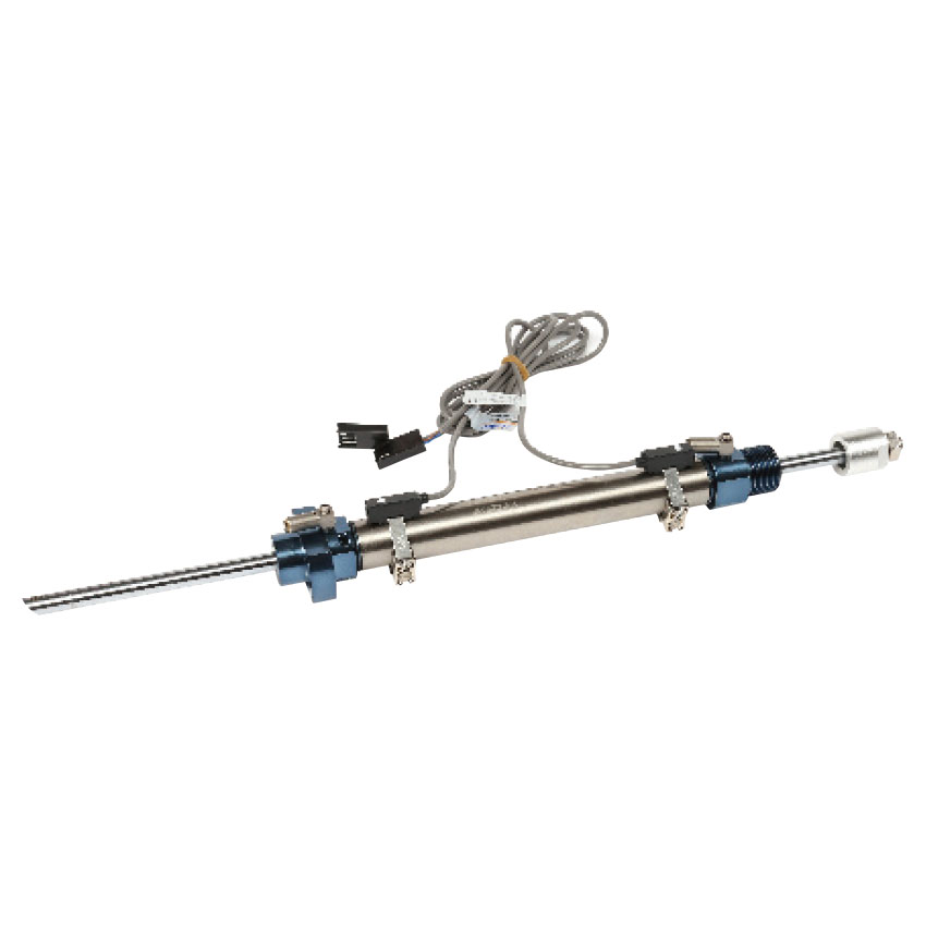
ABB angle sensor TGM5 refers to a sensor that can sense the measured angle and convert it into a usable output signal. As the name suggests, it is used to detect the angle. It has a hole in its body that fits the Lego shaft. When attached to the RCX, the sensor counts every 1/16th of a revolution of the shaft.
Install
1. Install the ABB angle sensor TGM5 on the boss and fix it on the metal plate with screws, nuts or pressure plates. During installation, it is strictly forbidden to process the shaft and casing, such as turning and drilling, so as to avoid the shaft or casing from being subjected to external impact force and pressure. ). It is strictly forbidden to loosen the screws on the sensor and turn the position of the tightening ring.
2. When connecting the sensor output shaft with other parts, it should be noted that the axis line should be kept in a straight line. If there is a deviation in the axis line, it is recommended to use adapters such as universal joints or bellows to avoid bending and deformation of the sensor output shaft. , damage other devices, thus affecting the use.
3. The sensor should be prevented from being invaded by water droplets, steam, solvents and corrosive gases, and metal chips or other powders should be prevented from entering.
4. The external wiring of the sensor should be welded at the waist groove of the lead-out end, and try not to be welded on the top of the lead-out end. Welding should use no more than 45W electric ferrochrome, and the time should be less than 5 seconds. The wire should not be pulled when it is welded or not cooled thoroughly, so as to avoid the brush wire or the entire terminal being pulled out or even falling off.
use
1. Use the angle sensor to control your wheels to detect obstacles indirectly.
2. If the motor ABB angle sensor TGM5 structure is running, but the gear does not rotate, it means that your machine has been blocked by obstacles.
3. The technology is very simple to use, and it's very good; one requirement is that the moving wheels don't slip on the floor (or slip too many times), otherwise you won't be able to detect obstacles.
4. This problem can be avoided if an idling gear is connected to the motor. The wheel is not driven by the motor but is driven by the movement of the device: during the rotation of the driving wheel, if the idle wheel stops, it means that you touch the motor. to the obstacle.
Recommended Products